|
|

| Fig. 1: Distribution of differences between corrected pointing data and the Model3 in both the coordinates plotted against the elevation. Linear trends can be clearly seen above about 40°. |
K.M. Borkowski
TRAO, Centre for Astronomy, NCU, Torun, Poland
|
In the beginning of September 2006 the Cassegrain mirror of the RT32 telescope
has been fixed to the support structure with the aid of four trusses. As expected,
this effectively removed the step seen in earlier pointing corrections of
the elevation coordinate. However this structural change of the telescope calls
also for a new pointing table. Here we report a first
approximation obtained by modification of the previously used model and based on over
600 new pointing measurements performed by the end of September 2006 with the
OCRA
receiving system (i.e. at 30 GHz). We find that small ad hoc amendments to
Model3
in both coordinates may be used for generating a provisional lookup correction table that
above about 40° seems already even better than the previous one. Also, trial fitting of
a completely new model has been carried out. Obtained solutions gave promising statistics
of the residual offsets (e.g. 0.005° rms) though, obviously enough, more measurements
are needed for a stable or reliable solution. More recently, a new analysis has been performed based on much richer data set and this analysis is presented at the very end of this report. |
The analysis of observational material that follows is done along lines similar to presented in an earlier report (based on this Polish version). Present data were different from previous in that they were obtained without any lookup table. Therefore after correction of measured data for neglected variable astronomical effects, a pointing model has been subtracted from offsets. Then the differences or residual offsets have been subjected to various analyses.
There were 654 records available for the presented analysis that have been
extracted by Roman Feiler from collected observational material.
Each record contained the UTC date and time of the measurement, source name,
telescope horizontal coordinates (i.e. azimuth and elevation) and offsets of
measured source position
from an a priori position in both the coordinates. This a priori position is known
to be generally (with a few exceptions) set without the use of any lookup table.
It was found that the time data do not excactly
correspond to the coordinates (from available values of coordinates it appears that
there are irregular time offsets of many
seconds between each of the coordinates and also relative to the UTC time given).
We believe this does not significantly affect the pointing offsets so that they can
be used for impovement of the pointing table. Nevertheless this
situation must be corrected since if there are any systematic errors in the a priori
positons on the sky generated by telescope control system, they would directly affect
the measured offsets, but now are completely neglected.
Before analysis records with obviously bad data were rejected. These were identified by offsets equal to 0 in either or both of the coordinates and also by abnormally high values of offsets (greater than 0.05° in absolute value in zenth distance or cosine scaled value in azimuth). The remaining 'good' records turned out to be 636 in number.
The measured offsets have been corrected as follows. For the UTC time found in the records and source coordinates taken from a J2000.0 catalogue we have computed rigorously apparent position (as seen at the location) of the source in the horizontal coordinates of the telescope geodetic location. Similar coordinates were computed in the way the control system (assumedly) computes the a priori position (the 'apparent' coordinates as the system understands them, i.e. the Alt-Az coordinates obtained from the equatorial source coordinates corrected only for the effect of precession from the catalogue epoch to the epoch of observations). The measured offsets were then diminished by the difference between the apparent and these a priori positions.
The computation of the mentioned apparent place involved the following effects:
| Precession, Nutation, Aberration of Light, UT1 – UTC Difference, Polar Motion, and Mean Atmospheric Refraction. |
In the final step so corrected offsets were further reduced by offsets predicted from a pointing model (essentially the Model3 without the 0.02° jump or its modified version, that we shall call Model4a, worked out in this analysis). These data are presented graphically below.
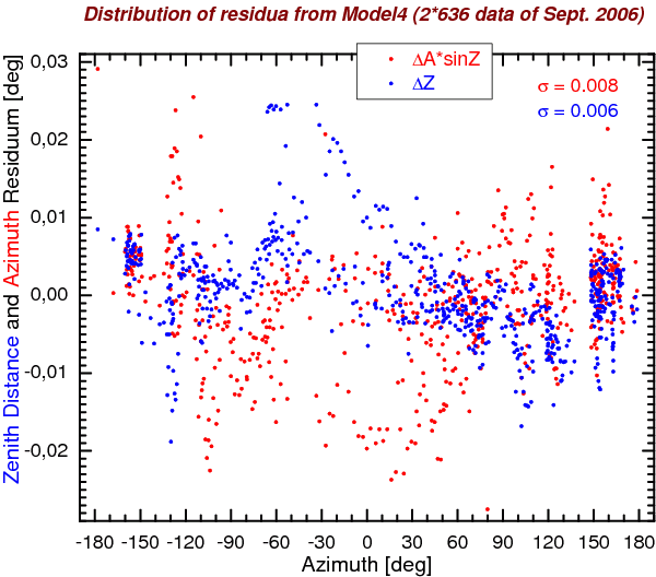
There are 39.6 % of cosine-scaled residua (remainders from subtraction of Model3 without the 0.02° jump) that exceed 0.01° (half of HPBW at 30 GHz) found for offsets in the azimuth coordinate data and 25.9 % such residua in the zenith distance offsets. The plot of Fig. 1 reveals similar systematic components present in both the coordinates. The slopes were estimated to –0.0004 °/° (i.e. degrees per degree of elevation).
|
| 0.02 – 0.0004 × Alt — correction
in zenith distance for 0° < Alt < 90°
0.009 / cos(Alt) — correction in azimuth for 0° < Alt < 90° |
The residuals resulting from subtraction of this corrected model, Model4a, cross the level of 0.01° for
7.9 % of 636 measurements in the zenith distance coordinate and
18.1 % of 636 measurements in the azimuth coordinate.
Although no doubt a great improvement to nearly 40 % seen with respect to Model3, yet these 18 % are certainly not satisfactory. For data with Alt > 42.5° (476 measurements of all the 636) these percentages reduce appreciably. In this region we have
3.2 % 0.01° crossings
in the zenith distance and
6.9 % in the azimuth
Considering that in the past (2003 – 2004) 11 % of data deviated from the Model3 by more than 0.01° present percentages seem acceptable (and better than before at altitudes higher than half-way to zenith). Also the zenith distance modeling presently look significantly better. Unfortunately, close to the horizon situation is opposite, worse than what we had before the fixation of the secondary reflector. One may expect that fitting of all model parameters to future new measurements will improve this state of affairs. Results of a preliminary fit (presented further down this page) are highly encouraging. For the fitting to be cosidered a lasting solution, more observations are required to fill the gaps in sky coverage. There is also a firmly grounded hope for better quality future observational data with the upcoming completely new telescope control program and improvements in procedures used for pointing observations.
|
|
In order to check if there is any dependence of pointing errors on the velocities
of the telescope drives we have plotted the distributions of residua with respect
to the respective sky velocities. The velocities in azimuth and zenith distance
depend on current source position in the horizon system of coordinates (see e.g.
Eqs. 4 and 5 in
this paper).
Apart from the at first quite intriguing gap at azimuthal velocities around 0.1 °/min
there are not any obvious dependencies. Perhaps larger dispersion in the neighbourhood
of diurnal sky velocity (0.25 °/min) is significant for the azimuth drive, but
the distribution there has
features that are evidently of non-stochastic nature and may result just from scarcity
of data and the fact that these data are composed of series of measurements that
are really not independent (same source, slowly changing offsets).
|
For completeness, in Fig. 5 we have also presented the distribution
of the same residua as a function
of accelerations in the two coordinates due to diurnal rotation of the sky. Necessary
mathematical formulae were again taken from already cited
reference [namely, Eq. 18 and the expression
z'' = A' cos(A) cos(φ) given in the paragraph preceding
Sec. 5 therein]. Those formulae give the accelerations in the naural units
(i.e. rad/rad2) which are inconvenient. Since the accelerations are very
small indeed and the usual units of 1°/s2 are very large, for our figures we
have converted them to smaller units. Our unit tells to how many degrees per hour
would a telescope increase its velocity in one hour moving with given acceleration.
The factor used for conversion from natural units was thus
(180/π)/(12/1.0027/π)2 = 3.94823.
|
The amended Model3, as described above, has been used to generate two varieties
of pointing look-up tables named model4a. They are suitable for the present
telescope control system (table step of 2°) and its successor being tested just
at this time (that uses model samples spaced 0.5°).
Although now it is probably premature to suggest a completely new solution
(due to still poor sky coverage), we have made a few trial fits to the new
data. The term of Model3 numbered 12 (as listed in this
table or in
the subroutine listings above that table) has been replaced by two new terms
with two coefficients to be fitted related only to the azimuth coordinate.
A few different formulations made such new model easily converge to
considerably better solutions than the above described amended model.
For example, the terms:
p(12)*sin(3*Az)*sin(Alt) + p(13)*cos(Alt)*cos(Az/4)
have led to a solution giving standard deviation of the residuals of about 0.005° in both the coordinates (though slightly higher in azimuth, 0.0052° compared to 0.0046° in zenith distance) and the count of 0.01° crossings has dropped to:
6.2 % in the zenith distance coordinate and
8.4 % in the azimuth coordinate.
For data with Alt > 42.5° these percentages were considerably smaller: 2.1 % and 4.4 % in the zenith distance and azimuth, respectively (which favourably compares with 3.2 % and 6.9 % of Model4a).
|
Similarly as with the Model3, we carried series of fits (three in this case),
and in all (save the first) iterations the measured offsets whose residua from previous
fit exceeded
in absolute value a predefined level have been heavily downweghted (by a factor of 1000).
For the final iteration this level was set at 0.013°. As a result, of 1286 offsets
analysed to the solution contributed effectively only 1253 (630 in zenith distance
and 623 in azimuth). The percentages of residua crossing 0.001° given above include
all the offsets (irrespective of this weighting), thus these
values are somewhat overestimated.
This temporary solution served for production of a new lookup table: model4b.
Here is a report on an update of the above described Model4b. This update, called Model4c,
has exactly the same parameter definitions as Model4b but the parameters (13 in number, the
12-th and 13-th differing from or in addition to
Model3)
were determined basing on enlarged set of measurements. The measurements were
done between 21 September and 12 December 2006. Considerable fraction of original
data had to be discarded prior to this analysis due to evident large errors. The errors
seem to be of two main kinds: an operator apparently have used an unspecified lookup
table (while he should have observed with a dummy table, i.e. without any pointing
corrections), or he
did not notice an error in the telescope computer time (such errors occur irregularly
and usually have magnitudes of a few seconds, but sometimes exceed 10 s). This is
unfortunate situation since not all of so spoiled data can be identified and thus
may have influenced also the presented solutions.
The preliminary data set, cleaned of bad observations, consisted of 1738 pairs of measured offsets, one each in the azimuth and zenith distance coordinate. Firstly we have checked how well these data are represented by previous lookup table (Model4b). It turned out that as much as about 35 % of offsets in azimuth were larger than 0.01°. This fact alone justified a more complete reanalysis.
Thus, these measurements were then fit to the model using the methodology of earlier fits, i.e initially weighting all zenith distance offsets equally and azimuth offsets according to the sin(z) law, and later heavily downweighting data that deviated more than a predefined level. This process of elimination of outliers resulted in effective rejection of 56 offsets of all the 3476. More specifically, the preliminary solution is a least squares fit to 1732 offsets in zenith distance and 1688 offsets in azimuth with the final RMS of these offsets of 0.0044° and 0.0059° in zenith distance and azimuth, respectively. The following table gives some more numerical results that speak of the fit and data qualities. These tabular data refer to full sets of measurements, and not only to those that contributed to a solution. The columns correspond to the previous (4b) and preliminary/final (4c'/4c) fit of the model 4c discussed in this section.
| Zanith distance | 4b | 4c' | 4c
| N(z) | 1738 | 1738 | 1655
| Mean [°] | 0.002 | 0.000 | 0.000
| RMS [°] | 0.005 | 0.005 | 0.004
| |dz| > 0.01° | 7.4% | 3.4% | 2.6%
| (for z < 47.5°) | 1.6% | 1.3% | 1.2%
| (for z > 47.5°) | 13.8% | 5.6% | 4.2%
| Azimuth |
| N(Az) | 1738 | 1738 | 1655
| Mean [°] | 0.003 | 0.000 | 0.000
| RMS [°] | 0.012 | 0.007 | 0.006
| |dAz| > 0.01° | 34.6% | 12.9% | 9.2%
| (for z < 47.5°) | 12.6% | 6.4% | 5.1%
| (for z > 47.5°) | 58.2% | 19.9% | 13.9%
| |
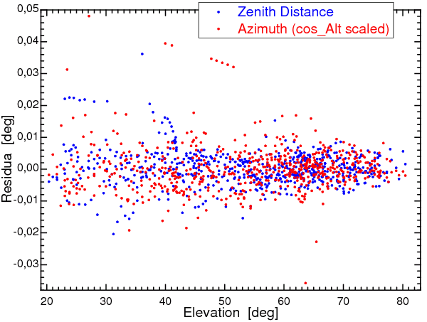
Note the difference in data qualities above altitude of 42.5° (where the percentage of deviations greater than 0.01° is about halved with respect to whole the hemisphere) that was seen also in previous analysis. This property is also clearly marked by smaller scatter in the distribution of residuals in the middle panel of Fig. 7.
|
Basing on the top graph of the above figure some more cleaning has been carried and in the process two complete series' of measurements most clearly departing from the fit were identified and removed from analysed data set. Then the fitting process to 3310 points has been repeated to arrive at parameters of the final solution that neglected further 27 points most outstanding from the best fit. This final solution has an overall rms of 0.005° and does not differ much from the preliminary one. So obtained new model parameters have been used to generate a lookup table named 'model4c'. The listings below show the parameters and extracts from the lookup table (except the values at z = 0.1° which do not belong to the table since the table contains data every 0.5° only).
      RT32 model4c parameters
      Fit of 3282 (1632+1650) points with RMS of 17.8" = 0.004949 deg
    1 Zero Az          (1)  -116.5+/- 9.6" = -0.032367+/-0.002678 deg
    2 Zero Alt=90-z    (1)  -177.7+/- 8.6" = -0.049374+/-0.002398 deg
    3 Skew Az     (tg Alt)   184.4+/- 7.2" =  0.051222+/-0.001987 deg
    4 Box  Az  (1/cos Alt)  -196.5+/- 8.9" = -0.054595+/-0.002480 deg
    5 Tilt South Az,Alt       -0.6+/- 0.5" = -0.000161+/-0.000141 deg
    6 Tilt West  Az,Alt       10.3+/- 0.6" =  0.002850+/-0.000157 deg
    7 Sag    Alt (cos Alt)     4.9+/- 6.6" =  0.001370+/-0.001842 deg
    8 Ad hoc Alt (sin Alt)    74.4+/- 6.3" =  0.020659+/-0.001762 deg
    9    "   Az  (sin 2Az)   -45.9+/- 0.9" = -0.012753+/-0.000261 deg
   10    "   Az  (cos 2Az)    30.9+/- 0.9" =  0.008571+/-0.000251 deg
   11    "   Alt (sin 2Az)    17.3+/- 0.6" =  0.004812+/-0.000177 deg
   12    "   Az (Alt,Az)     -23.3+/- 1.5" = -0.006485+/-0.000413 deg
   13    "   Az (Alt,Az)     102.8+/- 8.7" =  0.028568+/-0.002430 deg
     + Refraction in Alt

  Azimuth correction table extract   [units of 0.001 deg]:
   z\Az -180 -150 -120  -90  -60  -30    0   30   60   90  120  150  180
  -5.00  -17  -23  -27  -11   28   55   47   22    9    6   -2  -12  -17
   0.10 -324 -499-1060-1837-2629-3260-3583-3482-2946-2119-1253 -597 -324
  10.00  -28  -38  -58  -66  -52  -43  -59  -79  -76  -55  -38  -30  -28
  20.00  -28  -37  -54  -56  -39  -27  -41  -61  -61  -45  -33  -28  -28
  30.00  -29  -38  -53  -54  -35  -22  -35  -55  -57  -43  -31  -28  -29
  40.00  -31  -40  -54  -53  -33  -21  -33  -53  -56  -43  -32  -28  -31
  50.00  -34  -44  -56  -53  -34  -21  -33  -52  -56  -45  -34  -30  -34
  60.00  -38  -48  -59  -55  -36  -24  -34  -53  -58  -48  -37  -33  -38
  70.00  -43  -54  -63  -58  -40  -29  -37  -55  -62  -53  -41  -37  -43
  80.00  -50  -62  -69  -62  -45  -35  -43  -59  -67  -60  -47  -42  -50
  89.00  -57  -70  -77  -68  -52  -42  -49  -65  -74  -68  -55  -48  -57

 Zenith angle correction table (refraction included)   [0.001 deg]:
   z\Az -180 -150 -120  -90  -60  -30    0   30   60   90  120  150  180
  -5.00   30   25   24   27   32   33   30   27   28   33   37   36   30
   0.10   28   26   27   31   35   34   29   23   22   26   30   31   28
  10.00   26   23   24   29   33   32   26   21   20   23   28   29   26
  20.00   24   21   22   27   30   30   24   18   17   21   25   26   24
  30.00   21   19   20   24   28   27   22   16   15   19   23   24   21
  40.00   19   16   17   22   26   25   19   14   13   16   21   22   19
  50.00   16   13   14   19   23   22   16   10    9   13   17   18   16
  60.00   10    7    8   13   17   16   10    4    3    7   12   13   10
  70.00   -3   -6   -5    0    4    3   -3   -9  -10   -6   -1    0   -3
  80.00  -44  -47  -45  -41  -37  -38  -43  -49  -50  -46  -42  -41  -44
89.00 -310 -313 -312 -307 -303 -304 -310 -316 -317 -313 -309 -308 -310 |
| — KMB
(kb@astro.uni.torun.pl)
Posted 2006.10.18; last updated 2006.12.29 |


-4c.gif)
-4c.gif)
-4c.gif)